

PROCESS REENGINEERING AND QUALITY CONTROL IN A FOOD COMPANY
Cleaning cycle optimization:
experimental approach to clean the filling valve
Author: Francesco Quaretti
Academic Supervisor (USA): Paul G. Ranky, PhD, Full Professor, MIE Department (Mechanical and Industrial Engineering), NJIT, Public Research University of New Jersey, USA
Academic Supervisor (Italy): Andrea Volpi, Full Professor at University of Parma, Faculty of Industrial Engineering, Mechanical Engineering and Engineering for Food Industry Equipment
The goal of my Master's Project is to improve the semi-automatic cleaning system, making it more effective, finding a food compatible substance that can be used as a cleaning agent.
Abstract
The food sector has a fundamental importance in the Italian industry.
For this reason, this Master's Project talks about a work experience at Zilli&Bellini s.r.l, a famous company, that produce lines for filling and sealing food products in rigid containers. In this paper, we want to focus on a particular component of the piston filling machine: the filling valve. To date, the cleaning of the machine when you use the semi-automatic cleaning system is often faulty. An employee has to pull out the tap valves from their stainless-steel bodies to clean them manually. Therefore, we try to propose a solution that allows a faster cleaning and the possibility to reduce cleaning times.
The critical point is represented by the very thin air gap between the stainless-steel body and its polymeric tap valve that is free to rotate inside the steel body. Dirt and dangerous microorganisms can accumulate in this gap.
Our first goal is to find the most effective chemical solutions that can clean the thin gap and can be used compatibly in the food sector. Several laboratories suggest focussing on surfactant solutions or on solvents with low surface tension, that can penetrate in the gap and remove the dirt. In order to discover what is the best liquid able to penetrate in the gap we used an optical contact angle machine to analyze the contact angle between the droplet and the material surface. We tested: water, ethanol, solutions of water and ethanol in different ratio and surfactant soaps. For each liquid used, we calculated the contact angle, their degree of wettability and the economic efficiencies of their possible industrial use.
Finally, we chose the liquid with the best performance / economic viability ratio for a cleaning simulation on the piston filler prototype in a reduced scale. The solvent cleaning power is tested on different food products, to verify its effectiveness in every hypothetical situation.
Acknowledgements
-
A great thanks to Professor Paul G. Ranky for his vital support and assistance. His encouragement made it possible to achieve the goal of Master's Degree.
-
I want to thank Professor Andrea Volpi, who always gives me precious advice.
-
A special thanks goes to Dott. Corrado Sciancalepore, a great scientist who helped me with the wetting tests. I found him always available and ready to explain me new chemical topics.
-
Thanks to Chiara Valentini, a promising future management engineer. She is always with me and she believes in me.
-
I thank my Family for all support that give me. They are my life model.
-
Thanks to Martina Quaretti , my sister, a brilliant chemist.
-
Thanks to Zilli&Bellini s.r.l. because they accepted me, they made me available their software, their prototypes to do my tests and their company’s data. In particular, thanks to Massimo, Nicola, Andrea and Roberto, so gentle and polite with me.
-
The last thanks goes to Marco Riccardi, my friend which always remember me that the study and work is not everything in the life.
Table of Contents
1. Piston Filler
1.1 Components Description
1.2 The filling valve
1.2.1 Valve’s Materials
1.3 How the piston filler works
2. Problem statement
2.1 Zilli&Bellini cleaning system
3. Literature Survey
4. Solution
4.1 Methods: theoretical approach
4.1.1 Surface Free Energy (SFE)
4.1.2 Wettability
4.1.3 Surface Roughness dependence
4.2 Measurement of Contact Angle (CA)
4.2.1 Tool
4.2.2 Water on stainless-steel AISI 316L and PEEK surfaces
4.2.3 100% ethanol on stainless-steel AISI 316L and PEEK surfaces
4.2.4 Mixture of water and ethanol (10% v/v, 20% v/v, 40% v/v) on stainless-steel AISI 316L and PEEK surfaces
4.2.5 Mixture of water and surfactant soap (10% v/v, 20% v/v, 50% v/v) on stainless-steel AISI 316L and PEEK surfaces
4.2.6 Mixture of water, ethanol (10%) and surfactant soap (10% v/v, 30% v/v) on stainless-steel AISI 316L and PEEK surfaces
4.2.7 Results
4.3 Technology solution: experimental approach with piston filler prototype
4.3.1 Piston filler prototype
4.3.2 Food product: soy sauce
5. Suggested future work:
5.1 Laboratory tests with other liquids
5.2 Tests on the piston filler prototype with other food products and other mixture
5.3 Microbiological Challenge Test
5.4 Mechanical / pneumatic valve extraction system
6. References
1. Piston filler
Zilli&Bellini piston fillers are suitable to fill volumetrically all pumpable products. The machines can handle round and non-round metal, glass and plastic containers having a filling capacity up to 5 Kg. Their capacity is from 10 to 2200 c.p.m according to the product and container size.
Products that can be used are listed below [1]:
-
Apple juice
-
Baby food
-
Brine
-
Chocolate spread (one and two colors)
-
Concentrates
-
Condiments
-
Corn cream
-
Evaporated milk
-
Honey
-
Jams
-
Juices
-
Ketchup
-
Marmalade
-
Mayonnaise
-
Mineral oil
-
Mustard
-
Nectars
-
Pâté
-
Pet-food
-
Purée
-
Ratatouille
-
Sauces
-
Soups
-
Sweetened condensed milk
-
Vegetable oil
Table 1.1 shows the piston filler models at Zilli&Bellini company and their features.
In particular, we focus on DB piston filler model with 18 pistons.
Figures 1.1 and 1.2 represent the bottom view of the tank.
The working principle of this machine is simple: the pistons around the tank can be seen like giant syringes. When the filling valves are closed the pistons aspirate the fluid food from the tank, while the filling valves are open the pistons push down the food product inside the containers.
1.1 Components description
The machine is composed of a base made of a stainless steel AISI 316L frame and steel plates. The base is completely covered with AISI 316L stainless steel panels.
In the lower part of the base the adjustable support feet are screwed for height adjustment and machine leveling. (Figure 1.3)
The four sides of the base are closed by protective carter made of AISI 316L stainless steel mechanically locked, but easily removed by authorized personnel for possible maintenance interventions on the inside. Here there are the organs of the motorized units and transmission, the clutch star unit with devices for automatic stopping in case of anomalies.
Also in the lower internal part are installed the controls that allow the height adjustment of the filler and easy links with whatever completion units of the filling machine such as rinsing unit, deaerator, distributor, capping unit, inspection unit, wire-hooding, etc ...
The tank containing the food product is completely in stainless steel AISI 316L. The inside of this tank is entirely mirror polished to allow an easy and safe sterilization. The lid is hermetically sealed. This tank has been tested according to law regulations for pressures up to 8/10 Bar. (Figure 1.4)
The pistons are made by stainless steel AISI 316L. The pistons are inserted into two circular crowns around the tank to optimize the spaces and to be in a stable position contrasting the mechanical-pneumatic vibrations. They are connected to the tank thanks to the filling valves. (Figure 1.5)
When they go up, the food product is put inside the pistons’ cylindrical structure. When the filling valve is open, the pistons push down the food product inside the bottle or can or whatever container.
1.2 The filling valve
The filling valve is composed by two elements: the tap valve and the tap valve’s body, as shown below.
The tap valve is principally in PEEK (Polyether ether ketone), a colorless organic thermoplastic polymer in the polyaryletherketone (PAEK) family [2]. The tap valve has a cylindrical structure formed by two concentric cylinders; the stainless-steel one has the upper base settled with a cap in the same material. The most internal cylinder is made of stainless steel AISI 316L, because it is the part in contact with the food product. Externally there is the PEEK cylinder. These two cylinders are united thanks to the polymer’s thermal dilatation, thanks to the use of glue substance and thanks to stainless-steel’s superficial roughness that creates friction against the PEEK. (Figure 1.6)
The tap valve is created in this way: the PEEK cylinder is heated at 135°C per 12 minutes to allow the polymer thermal dilatation. While the polymer cylinder is still hot and its radius is increased, the stainless-steel cylinder is inserted inside. On the external rough stainless-steel surface, a glue substance has been spread to help the cohesion between PEEK material and the cylindrical external area of the stainless-steel. Both cylinders have three holes. In the biggest one, the food product flows due to the suction of the pistons and it fills the cylindrical structure in which the pistons can move. The other two holes create a passage in which the product, which has just been aspired, can be pushed down from the pistons into the bottles or other containers.
The other element that composes the filling valve is the stainless-steel tap valve's body. It is mounted by four screws to the tank, because its function is to link the tank with the pistons. Inside the tap valve's body, the tap valve is free to rotate. When the filling valve is open, the rotation of the tap valve inside its steel body allows the alignment of the two holes and the passage of product from the pistons’ cylindrical support to the container. When the filling valve is closed, the tap valve rotates in such a way as to put the pistons in communication with the tank, orienting the holes to allow the food product to be aspired into the cylindrical structure in which the pistons move.
1.2.1 Valve’s material
Several studies and laboratory tests highlighted that the materials more suitable for the filling valve's creation are PEEK and stainless-steel AISI 316L. Many other materials were rejected because they did not meet the construction needs.
This valve must be resistant at high temperature, must have great wear resistance and above all, it must be suitable for food treatment.
The filling valve, as described above, is made of two different materials, one that rotates inside the other one. For this reason, the choice of materials must consider the strong friction generated during the rotation.
The materials must also be easily available, without high costs and must be easy to work.
Polyetheretherketone (PEEK) is a high performance and high temperature semi-crystalline thermoplastic. The most well-known and important member of the polyaryletherketone group combines excellent wear, and very good mechanical properties, even under thermal load. Outstanding chemical resistance and a high operating temperature (up to 260°C) round out its profile and make PEEK an almost universally appropriate material for highly stressed parts. Its excellent dimensional stability combined with high creep stability supports the suitability of PEEK for the most sophisticated machined parts [3].
Its main features are summarized below:
- Excellent chemical resistance
- High thermal resistance
- Good heat deflection temperature
- Good machinability
- Very good slide and wear properties
- Hydrolysis and superheated steam resistant
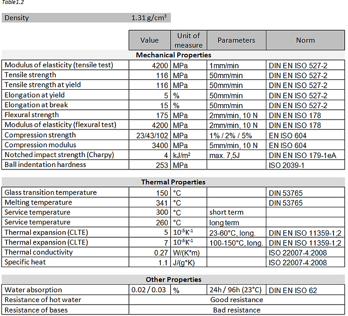
In Table 1.2, the most relevant properties of PEEK material for the design and functioning of a valve. These data derive from the supplier’s data sheets that produces PEEK material [4].
The stainless-steel AISI 316L is a type of steel in which the letter “L” means Low Carbon.
It’s very similar to the 304 one, but it is more difficult to corrode because it has a lower carbon percentage, useful to prevent the precipitation of chromium carbides and therefore corrosion. Both steels are used and indicated for food processing.
In the Table below the chemical percentage composition that characterize stainless-steel AISI 316L [2].
The fundamental properties of this austenitic steel are:
- Excellent resistance to corrosion;
- Easy cleaning and excellent hygiene coefficient;
- Easily machined, forged and weldable;
- In conditions of total annealing it does not magnetize.
- Wide use range from 700 °C to use in cryogenic systems
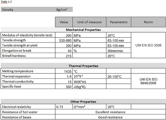
In Table 1.3, the properties most relevant to the function that the stainless-steel AISI 316L will have in the filling valve, have been selected and listed. These data derive from the supplier’s data sheets that produces AISI 316L steel [5].
1.3 How the piston filler works
The filling machine’s scope is to fill rigid containers with several food products (liquid or semi-solid with a different viscosity degree). In fact, the piston filler works with food product of different nature: we can have liquid products like juice, semi solid products with low viscosity like soups and mineral oil and other ones with high viscosity like marmalades and pâtés.
Empty containers, previously cleaned and sanitized, are placed on a conveyor belt. At some point the conveyor belt becomes thinner; the funnel shape allows the passage of one container at a time into the bottleneck. The single row sorting of containers takes place thanks to small side rollers which neatly convey the container towards the bottleneck. The rollers also serve to prevent that fragile containers collide with each other with the occurrence of a damage or a break. One by one the containers are taken by a rotating star, synchronized with the central filling star. This rotating star brings the containers under the filling valves. Here the filling takes place: the food product from the tank is pushed inside the container by the pistons. The pressure exerted by the piston allows to perfectly dose the food quantity pushed into the container.
Another star, rotating in a synchronized way with the central filling star, takes the filled containers and places them on a conveyor belt. The DB model described in this paper has not an integrate closing or seaming system. For this reason, the customer must support this piston filler with an extra machine that hermetically closes the containers just filled.
The video below shows the functioning of the piston filler machine described above.
.png)
.png)
.png)
.png)
.png)
.png)
.png)
.png)
.png)
2. Problem Statement
To maintain continuative working cycles, plant cleaning must be carefully planned. In food and beverage industries, where hygiene is crucial, the cleaning in place (C.I.P.) system is used to clean the important parts of the plants instead of manual or semi-automatic cleaning. A mix of chemical products, heat and water cleans machines, tanks and pipes, without having to dismantle the plant. We talk about a very efficient washing method, which, in the long term, permits saving time and money. The insertion of an automatic washing system (C.I.P.) in the system reduces the times of the washing phase, thus increasing production.
It maintains quality; effective washing eliminates product residues due to potential contamination.
The C.I.P. is a closed system in which sanitary conditions are easier to maintain, safety operations are increased, and maintenance costs are reduced.
The Zilli&Bellini automatic cleaning system uses superheated water and caustic soda (2%). This basic solution is perfect and efficient in all their machines such as handpack fillers or automatic rotary telescopic and semi-telescopic fillers.
If the customer does not want to buy the additional C.I.P. unit, the Zilli&Bellini machines have a semi-automatic washing system in any case. But this semi-automatic washing system has inefficiencies in the cleaning of the piston filler. Despite the wash cycle is performed correctly, sometimes the filling valve remained dirty.
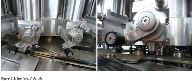
The critical point is represented by the backlash between the tap valve and its steel body. In this interspace of about 80 μm the food product accumulates and if not properly cleaned becomes a source of contamination. This dirt cannot be cleaned only with the action of water, nor with the use of caustic soda solution. This problem often forces the customer to use a C.O.P. system (Clean Off Place), only to clean the filling valves, because the semi-automatic system failed. In this case the workers must remove the tap valve from its steel body and must clean these two parts again with a pressure washer. The tap valve removal consists of unscrewing the tap lever that holds press the tap valve inside its steel body. (Figure 2.1)
This manual procedure requires a loss of time.
2.1 Zilli&Bellini cleaning system
Zilli&Bellini offers customers two washing systems.
The first is automatic. Thanks to the use of a C.I.P. unit flanked to the filler, a washing cycle can be created that crosses water, superheated water and caustic soda 2% solution. This automatic method is almost infallible. If a piston filler is flanked by a C.I.P. system produced by Zilli&Bellini, it is very difficult for the filling valves to remain dirty. This washing system is very efficient. (Figure 2.2)
The C.I.P. unit is a machine that allows to clean and sanitize entire filling plants, without them having to be dismantled. It is an external unit that you can add to any other machine produced by Zilli&Bellini. It allows the use of caustic soda and acid solutions before a plentiful water rinsing.
The C.I.P. unit for the washing of the systems allows to prepare, automatically, the washing and disinfection solutions, to carry out the planned cycle and to verify that this cycle has been effectively completed according to the expected modalities.
The goal is to eliminate all sorts of residual products from the plants, both at the end of the shift and in the product change phase. The mechanical washing action with high flow rates, combined with the chemical action of detergents and disinfectants, allows you to thoroughly clean even the most critical parts of the plants.
The other washing method (the semi-automatic washing system) is included in every machine and it represents a middle ground between a totally automatic cleaning system (CIP) and a manual one.
It is called semi-automatic because it is a system that needs in any way the presence of a worker. The difference between the CIP system is that the CIP is more automatic than the semi-automatic system. In fact, once the CIP starts its washing cycle, the additional cleaning machine works without the presence of a worker. The other great difference between the two systems is that CIP allows the use of high temperature and pressure water.
On the other hand, the semi-automatic system, compared to the totally manual one, is faster, requires less labour and provides less waste of water during rinses.
This method allows the use of water at room temperature and caustic soda 2% solution
The semi-automatic system is based on a recovery tank flanked by a pump that allows the recirculation of water or detergents between the recovery tank and the tank. In this way are created the loops that move the same fluid between the two tanks. (Figure 2.3)
.png)
.png)
.png)
.png)
Under the tank there is a collection tank (always in AISI 316L steel) that ends with a drain opening.
(Figure 2.4)
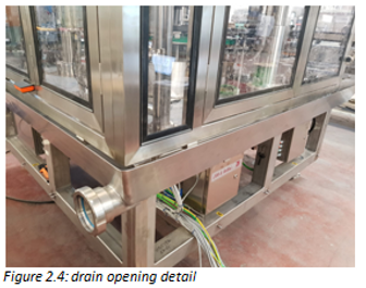
A worker mounts the first mobile pipe to this drain opening in order to connect the recovery tank with the collection tank. (Figure 2.5)

The newly mounted mobile tube has a three-way valve, two ways that link the tank with the collection tank and the other way from which the drain pipe starts. (Figure 2.6). The drain pipe is a mobile pipe that connects the collection tank to a container for the disposal of chemical products used during the cleaning cycle. Then the operator must mount the drain pipe to allow the discharge of chemical detergents used for cleaning.

At the end, the third pipe, called recirculation pipe, is mounted by the operator to put the pump in communication with the tank.
Figure 2.7 is a simple diagram that shows the components of the piston filler that have a major role during the cleaning cycles in the semi-automatic system

The semi-automatic system has several steps to complete a cleaning cycle.
i) The piston filler is switched off. The filling valves and the big valve under the tank are open to release the remaining food product residue.
ii) While the piston filler continues to be inactive, all the previously opened valves are closed again.In the same pipe in which the food product flowed, the water is forced to flow and fill the tank from the top, but without exceeding the overflow limit.
iii) Suddenly the big valve is opened. The mass of water previously collected in the tank empties and brings with it the coarser residues of the food product.
iv) The big valve is closed. The tank is filled with water up to about half its volume. The piston filler is switched on and the filler valves start to expel the water due to the thrust of the pistons just actuated. The three-way valve is set to block the passage to the drain tube and put the collection tank in communication with the recovery tank. The water expelled from the filler valves is collected in the collection tank and arrives to the recovery tank. The pump that flanked the recovery tank aspires and pushes the water back into the tank through the recirculation pipe. The rinse loop of water is created. When this phase is ended, the big valve opens and water flows quickly into the drain tube because the three-way valve isolates the recovery tank from the collection tank.
v) The piston filler is stopped, so the valves and pistons remain stationary. The three-way valve is again set to connect the collection tank and the recovery tank. From the top, the water fills the tank up to a pre-established value which stops the supply. At this point the piston filler turns on and the water recirculation starts with the same modalities written in the phase IV. An operator inserts an aqueous solution of soda directly into the recovery tank in order to recirculate this basic agent with cleaning action. Once the duration of this phase is ended, the three-way valve changes its position and the water-soda mixture flows from the collection tank to the container for disposal through the drain pipe.
vi) The last phase is formed by two rinses with water with the piston filler always on. The first consists of a short water recirculation to remove the traces of soda from the surfaces and pipes. The second following is not a recirculation, but the water, after having wet the tank and the filler valves, is collected in the collection tank and is discharged passing through the drain pipe. Between the first and second rinse the position of the three-way valve has changed.
Despite these steps, filling valves often remain dirty.
3. Literature Survey
In a food sector, it is essential that the plant that processes the food product is designed to be as efficient as possible. The key parameters for the design of these types of machines are for example, the production speed, the energy efficiency, the use of wear-resistant materials and many other factors that determine whether this machine will beat the competition in the selling market.
But this is not all, as well-treated in the HJ Heinz, Chapter 4: “Buildings, design and construction” in Principles and Practices for the Safe Processing of Foods, edited by David A. Shapton and Norah F. Shapton, Butterworth-Heinemann Ltd, 1991 [6] the design of a machine must also consider its easiness and practicality cleaning. In the food sector, washing systems have an absolute importance. I believe that Chapter 5 "Why we clean?" summarizes the reason for such attention to cleaning and sanitizing machines, tools and workplaces that meet food products.
In general, this book was my starting point for the selection of my challenge for this Master's Project. I consulted it for various topics. The search for the solution to my challenge is very practical and includes wettability tests in laboratory, verification tests on a piston filler’s scale prototype and a Microbiological Challenge Test to validate the plant.
Many experiments in measuring the contact angle and the relative wettability of the tested surface are reported in scientific literature. In my opinion, M. Kalin and M. Polajnar, "The wetting of steel, DLC coatings, ceramics and polymers with oils and water: the importance and correlations of surface energy, surface tension, contact angle and spreading”, Applied Surface Science,Vol.293, pp.97-108, February 2014 [7] is one of the most complete and interesting paper to use for my research.
I also want to mention Yuehua Yuan and T. Randall Lee, Chapter 1: “Contact Angle and Wetting Properties”, in Surface Science Techniques, by Gianangelo Bracco, Springer Series in Surface Science, Vol. 51 , Gianangelo Bracco and Bodil Holst Editors, 2013 [8] which explains the different methods of measuring the angle of contact. In the initial part, it mentions topics closely related to wettability such as surface tension, the Young equation and Contact Angle Hysteresis.
Using as reference the Jaroslaw Drelich, "Guidelines to measurements of reproducible contact angles using a sessile-drop technique " in Surface Innovations, Vol. 1, Ice Publishing, pp. 248-254, December 2013 [9], I learned how to use the optical contact angle machine correctly.
However, this engineering problem of food valves cleaning treated in my Master's Project has not particular evidence in the scientific literature and it has often been difficult to find paper about it.
I found two interesting articles that show two different inventions for a cleaning method on a piston filler: Jean-Claude H. Hautemont, “Cleaning system for filler”, US Patent number: 4,534,494, assigned by Societe Anonyme Dite: Etude Et Realisation De Chaines Automatiques ERCA, Orsay, France, Date of Patent August 1985 [10] and Stanley A. Groom,” Cleaner for filler nozzles”, US Patent number: 4,987,934, assigned by FMC Corporation, Chicago, Unites States, Date of Patent January 1991 [11].
In this Master's Project I could not change the Zilli&Bellini design of the washing system, nor the shape of the filling valve, therefore I tried to find an easy and economical solution for the problem of food accumulation in the valve interspace. Therefore, I selected a series of possible effective cleaning agents and I studied their properties and material interactions with different laboratory tests to find the cleaning fluid most suitable for my purpose.
4. Solution
The purpose of this Master’s Project is formed by two aspects: one in which the data are been collected, and in the other one an operative approach was used. In detail, in the theorical approach it was necessary described everything that concerns the cohesive and adhesive forces, surface free energy (SFE), wetting grade, contact angle and the equations that represent the correlations between these factors. In this way I can select the most correct liquid for this Master’s Project challenge: the filling valve’s cleaning.
4.1 Method: Theorical approach
4.1.1 Surface Free Energy (SFE)
When a drop of liquid is deposited on a solid surface, the liquid can spread on the surface (the best-known example is water), or it can structure itself forming a drop (how does mercury).This different behavior depends on the intensity of the cohesion and adhesive forces.
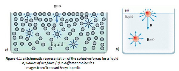
At a microscopic level, molecules can chemically interact each other, forming primary bonds (i.e. ionic or covalent interactions) and secondary electromagnetic bonds (i.e. hydrogen interactions or Van der Waals force). The attraction between molecules of the same substances is called cohesive force. (Figure 4.1 a). In a solid, these forces prevail over the others, such as the molecules kinetic or potential energy. For this reason, the solids are able to preserve, unlike gas and liquids, a proper shape. Each solid molecule is attracted by the surrounding molecules with the same intensity. These conditions enable each molecule of the solid, surrounded by other solid molecules, to be subjected to a no force. Instead a molecule on the surface is subjected to a force directed towards the inside of the solid, because the net forces (R) is not zero like in a bulk.
For this reason, the gas molecules at the interface with a solid body are not able to attract the molecules on the solid surface because this interaction is lower than the cohesive force presents between the solid molecules in a bulk. This attraction between molecules of different substances is called adhesive force. (Figure 4.1 b) [2]
.png)
After these considerations, the increase of the solid free surface cannot occur spontaneously.To move a molecule from the bulk to the surface it is necessary to work against the cohesion forces; the solid free surface is enhanced by making a work that, for this reversible and isothermal process, can be expressed as:
dW=𝜏 dA.
𝜏 indicates the surface tension of the solid (or surface free energy SFE) which is a function of various parameters, including the nature of the solid, the gas or liquid in contact with the solid surface.
From the dimensional point of view the Surface Free Energy (SFE) can be expressed as:
The official units of measurement in the SI system are N/m. Historically, however, the most commonly used unit of measure is: dyne/cm (1 dyne/cm = 1 mN/m).
The concept of SFE is valid for both solids and liquids. The only variation between the two cases is in the value of the surface tension. Because of surface tension, a liquid tends to minimize its interfacial surface assuming a spherical shape (droplet). In fact,the sphere is the solid with the volume/ surface ratio bigger.
We can imagine the superficial tension as the force that holds together the molecules of a liquid or a solid. If in a liquid its surface tension is high, this liquid has the tendency to form an almost perfect spherical drop in contact with a solid surface. Vice versa, a liquid with a low surface tension tends to spread on the solid surface forming a film.
Therefore, the wettability of a liquid is related to its surface tension: the lower the surface tension and the higher is the tendency to wet a solid surface.[12]
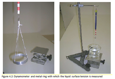
The study of liquid surface tensions takes place through a direct method, from which the value of the surface tension is measured with a process that requires a sensitive dynamometer and a metal ring with a diameter of a few centimeters. The ring is connected to the dynamometer with suspension wires: the elongation of the dynamometer gives a measure of the weight (F1) of the ring. In order to measure the surface tension without suffering the effects of the hydrostatic force, the ring is immersed in the liquid and then extracted. An increasing elongation of the dynamometer is observed, up to a maximum value F2. The difference F2 - F1 gives the force with which the surface tension acts on the ring.To obtain 𝜏, this value must be divided by the length of the affected section which is twice the circumference of the ring.If r is the radius of the ring, the value of the surface tension will be:
.png)
.png)
.png)
Instead the determination of solid surface tension takes place through measures deriving from the liquid application on solid surfaces. In particular, the wettability of the solid is studied, using the measurement of the contact angles between the solid surfaces and the drop of liquid deposited.
This method is indirect, because it allows to calculate the solid surface tension starting from the estimate of the solid adhesive and cohesion forces with liquids, whose surface properties are known.
4.1.2 Wettability
Solid wettability is the process that describes the contact of a liquid with a solid surface. This occurs in the presence of a gaseous phase or liquid phase (fluids) which are immiscible with the wetting fluid in analysis.
A drop of a liquid deposited on a solid surface adheres to it depending on the liquid and solid nature. This phenomenon also depends on the balance between cohesion forces (between molecules of the same substance) and adhesive forces (between molecules of different substances).
When the adhesive forces are greater than the cohesion forces, the liquid tends to wet the surface forming a film, while when the adhesive forces are lower than those of cohesion, the liquid tends to "reject" the surface and form a drop.
Figure 4.3 summarizes the dependence between the forces and the wettability grade.
.png)
Wettability is fully described by the contact angle, defined as the angle formed by the encounter of the liquid-air interface with the liquid-solid interface.
At the equilibrium condition, the contact angle assumes a value between 0 ° and 180 °.
The Figures 4.4, 4.5, 4.6 and 4.7 show the several situations that a liquid droplet can have in contact with the solids.
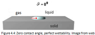
The wettability is maximum when θ = 0° and is due to a low liquid surface tension and therefore to a large solid surface tension.
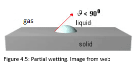
The wettability is partial when 0°<θ <90 °.
A low contact angle indicates good adhesion, good wetting and high surface energy.
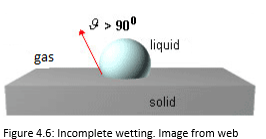
The wettability is incomplete when 90°<θ <180 °.
A high contact angle indicates bad adhesion, bad wetting and low surface energy.
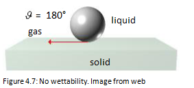
The wettability is minimal when θ = 180° and is due to a high liquid surface tension and therefore to a small solid surface tension [13].
The Table 4.1 highlights the dependence between the contact angle and the adhesive and cohesive forces of the liquid-solid system.


Figure 4.8 shows that high-energy surfaces have chemical bonds (covalent, ionic or metallic) that hold atoms together and are very strong. Many liquids can completely wet a high-energy surface (eg. metals, glasses, ceramics). Low energy surfaces have molecules that are held together by forces of a physical type (van der Waals bonds and hydrogen bonds). These bonds are easy to break providing low energy.These surfaces can allow incomplete or partial wettability depending on the type of liquid.(eg. molecular solids, ice)
4.1.3 Surface Roughness dependence
In ideal conditions the wettability measurements should be conducted on perfectly flat surfaces. However,in reality few surfaces are really flat and therefore it is necessary to consider their roughness.
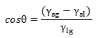
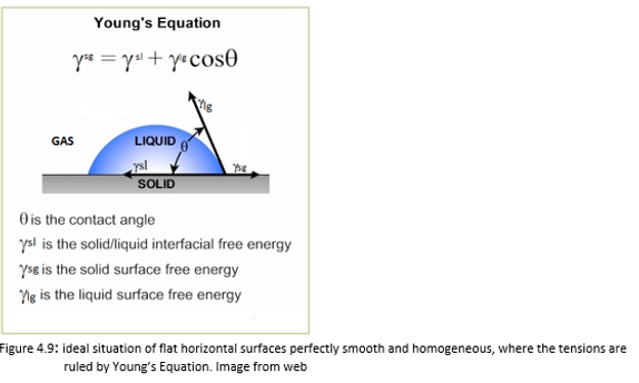
In the ideal hypothesis of flat horizontal surfaces perfectly smooth and homogeneous, the system is composed of three phases: liquid (the droplet), solid (the surface on which the droplet rests), gas (air). Consequently three interface zones are formed: liquid-solid, solid-gas, liquid-gas.The relative surface tensions act on each interface.At the intersection of the three interfaces (triple point), simultaneously the solid-liquid surface tension (γsl), the surface solid-gas tension (γsg) and the liquid-gas surface tension (γlg) act. These superficial tensions are respectively direct towards the inside of the drop,towards the outside of the drop and along the tangent to the drop at the point of contact.(Figure 4.9)
In this case the balance of the tensions and the contact angle are expressed by Young's equation:
The most realistic case is represented by a droplet deposited on a flat and rough horizontal surface.In this case on the surface there may be chemical or physical differences and defects. For this reason, it is necessary to introduce a distinction in the concept of a superficial area. The projected surface area (called also apparent or geometric surface area) is defined as the projection of the drop on the geometric plane of the surface, that is the area that appears to be macroscopically wet by the drop.
Instead a real surface area is the area of the surface really wet of the drop, considering its roughness and not a projection.
The parameter that describes the droplet-solid system is the ratio between the real surface area and the projected area, indicated with r.
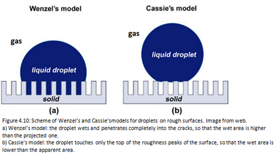
In the Wenzel’s model the liquid droplet is in contact with all the points of the surface. The true surface area is greater than the apparent area, therefore r> 1.In this case the contact angle is given by the Wenzel’s law:
where θ is Young’s angle and θw is Wenzel’s angle (or apparent angle). (Figure 4.10a)
In the Cassie’s model the liquid droplet does not wet the entire surface below, but only the peaks of surface roughness, leaving air or gas trapped between them. In fact, the surface behaves like a heterogeneous surface composed of its material and air. The contact angle is given by the Cassie’s equation:
where θ1 is the contact angle of the component 1 with fraction area f1, and θ2 is the contact angle of the component 2 with fraction area f2 present in the composite material.
Therefore f1 + f2 = 1. (Figure 4.10b) [14]
In this Master's Project the wettability tests were carried out on samples of PEEK and stainless-steel AISI 316L considering the surfaces of these two materials as ideal (homogeneous and free from roughness surfaces).
4.2 Measurement of Contact Angle (CA)
4.2.1 Tool
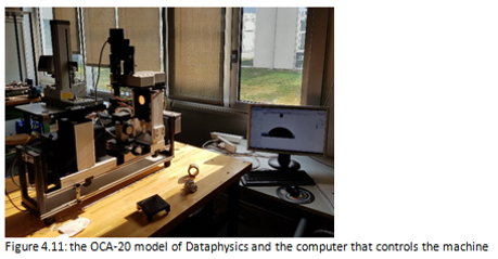
The contact angle measurements were conducted using the OCA-20 model of Dataphysics following the "sessile drop" procedure using 1μl drops dispensed at a rate of 1 μl/s on the surface of the materials to be analyzed. (Figure 4.11).
The sessile drop technique allows to observe the shape of the droplet deposited on the surface using an optical microscope.
The machine used consists of: an electronically controlled syringe pump, an apparatus for the droplet photo on a horizontal surface and a software for the analysis of the contact angle. (Figure 4.12)
The sample is placed on a horizontal support, height adjustable by a screw. The drop is deposited on the sample through a syringe moved by an electric motor controlled by a computer that allows to dose the volume of the drop with a sensitivity of 200 nl. The droplet is backlit by a led lamp that is connected to a potentiometer, which allows to adjust the brightness. Getting a good contrast means to easily determine the profile of the droplet. The droplet is photographed by a digital camera positioned opposite the lamp. The camera is mounted on a micrometric handler that allows lateral movement and easy focusing. A software allows the live acquisition of the image through the recognition of the droplet profile by analyzing the contrast of the image pixels.

For each sample of PEEK and stainless steel AISI 316L (materials that form the filler valve), thirty drops were dispensed at different times and the contact angle (CA) was calculated from the software. The final value was obtained as average of the values of these thirty measurements. Each media was compared to the others obtained by changing the materials, substances and concentration percentages.
4.2.2 Water on stainless-steel AISI 316L and PEEK surfaces
Water was the first liquid to be tested because easily available and low-budget.
In this way I could understand the hydrophobic or hydrophilic behavior of stainless steel AISI 316L and PEEK.
According to literature, these tested materials show hydrophilic properties.
Table 4.2 describes the conditions in which the wettability tests were performed.
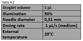
Only for the wettability test with water the diameter of the syringe is equal to 0.31 mm, because the water having a low surface tension, does not have difficulty to descend from the syringe needle and detach from it and then settle on the sample.
As described below, for the wettability test with ethanol and anionic surfactant, the used syringes have a diameter of 0.51 mm, higher than those for the water wettability test.
This is due to the high surface energy that keeps the droplet sticking to the outside of the needle, making it difficult to remove it.
Table 4.3 reports the measurement values for the left and right contact angle of the droplet. The more the discrepancy between the values of the right and the left is small, the more accurate the measurement is.
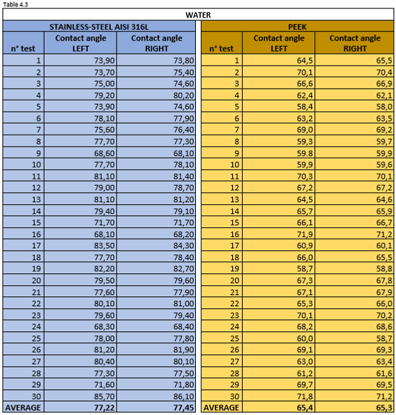
Figure 4.13 shows a water droplet on stainless steel AISI 316L (left) and PEEK surface (right).

In both materials the water drop forms a very high contact angle, which makes it unsuitable to penetrate the thin gap between the tap valve and its steel body.
However, water is an excellent solvent in order to create a mixture with a contact angle low enough for this Master’s Project challenge.
4.2.3 100% ethanol on stainless-steel AISI 316L and PEEK surfaces
Ethanol, also called ethyl alcohol is a chemical compound, a simple alcohol with the chemical formula C2H5OH and it is often abbreviated as EtOH. Ethanol is a volatile, flammable, colorless liquid with a slight characteristic odor.
Ethanol is naturally produced by the fermentation of sugars by yeasts or via petrochemical processes.
It also has medical applications as an antiseptic and disinfectant. The compound is widely used as a chemical solvent, either for scientific chemical testing.
Table 4.4 shows the conditions in which the wettability tests were performed.

Table 4.5 reports the measurement values for the left and right contact angle of the droplet.

As shown in literature, the contact angle that forms ethanol with polymeric surfaces or steels is small. 100% pure ethanol wet better the samples than water.
Figure 4.14 shows an ethanol droplet on stainless steel AISI 316L (left) and PEEK surface (right).

4.2.4 Mixture of water and ethanol (10% v/v, 20% v/v, 40% v/v) on stainless-steel AISI 316L and PEEK surfaces
The addition of a percent of ethanol to water sharply reduces the surface tension of water. For this reason, I decided to carry out a lot of wettability tests in which I tried three mixtures of water and ethanol in different volumetric ratio:
- 10% ethanol + 90% water
- 20% ethanol + 80% water
- 40% ethanol + 60% water
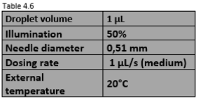
Table 4.6 shows the conditions in which the wettability tests were performed. These values are the same for the three mixtures.
Tables 4.7, 4.8, 4.9 report the measurement values for the left and right contact angle of the droplet for the three mixtures mentioned above.

Figure 4.15 shows a 10% ethanol mixture droplet on stainless steel AISI 316L (left) and PEEK surface (right).

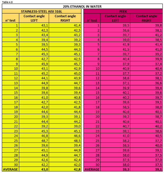
Figure 4.16 shows a 20% ethanol mixture droplet on stainless steel AISI 316L (left) and PEEK surface (right).
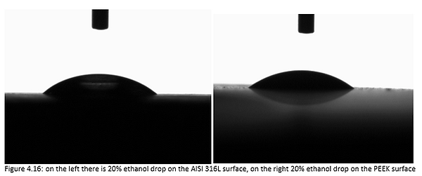
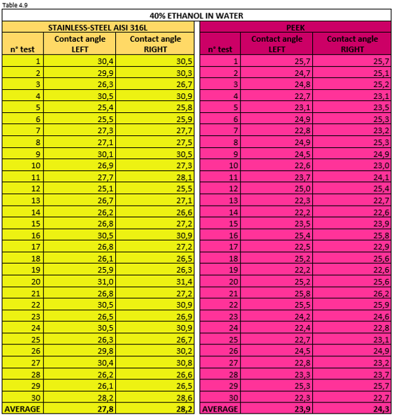
Figure 4.17 shows a 40% ethanol mixture droplet on stainless steel AISI 316L (left) and PEEK surface (right).

Figures 4.15, 4.16 and 4.17 are the photos of the drops of ethanol-water mixture deposited on the materials forming the valve. From these photos we can clearly see the profile of the droplet which, as the ethanol concentrations increase in water, becomes lower.
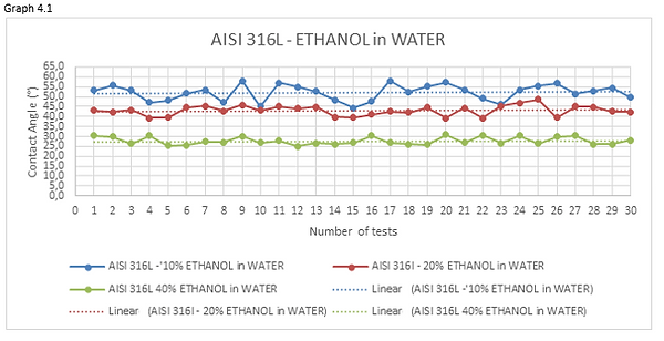
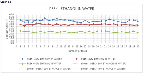
Looking at the graphs 4.1 and 4.2 we can see how the curve, representing the measurements of the 10% ethanol-water mixture, has an average value of contact angle higher than mixtures having a percentage of ethanol dissolved in water greater.
4.2.5 Mixture of water and surfactant soap (10% v/v, 20% v/v, 50% v/v) on stainless-steel AISI 316L and PEEK surfaces
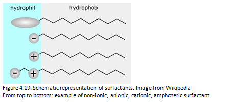
The addition of surfactants modifies the wetting properties of the water. The drop placed on a poorly wettable solid surface is initially spherical. However, the presence of surfactant in the water causes the flattening of the drop, increasing the wettability of the solvent. Surfactants are molecules composed of a hydrophilic head (for polar solvents such as water) and a hydrophobic tail (affinity for lipids, rejects water). In this way they have a balance between lipophilic and hydrophilic properties and allow the removal of dirt from surfaces.
The surfactant molecules dissolved in water are arranged with the hydrophilic head towards the water and the hydrophobic tail towards the surface of the container. When the surface of the container is completely occupied, the surfactant molecules are associated with each other forming aggregates of colloidal dimensions called micelles. (Figure 4.18)

When a surfactant solution encounters dirt, these molecules surround the dirt particles with their hydrophobic tails. The hydrophilic heads attract dirt to the water and help to detach it from the surface. The crown of hydrophilic heads carries the dirt particles in the water, where they end up in suspension and then float in the water [2].
There are different types of surfactants. In this Master's Project was used an anionic surfactant for industrial use, permitted for cleaning surfaces for food contact. (Figure 4.19)
Anionic surfactants have a negative charge in the polar head.They were the first to be used in detergents and are still the most used thanks to their excellent washing and foaming properties and low cost.
I decided to execute a lot of wettability tests in which I tried three mixtures of water and surfactant in different volumetric ratio:
- 10% surfactant+ 90% water
- 20% surfactant+ 80% water
- 50% surfactant+50% water
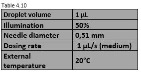
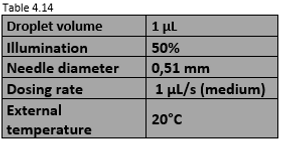
Table 4.10 shows the conditions in which the wettability tests were performed. These values are the same for the three mixtures.
Tables 4.11, 4.12, 4.13 report the measurement values for the left and right contact angle of the droplet for the three mixtures mentioned above.
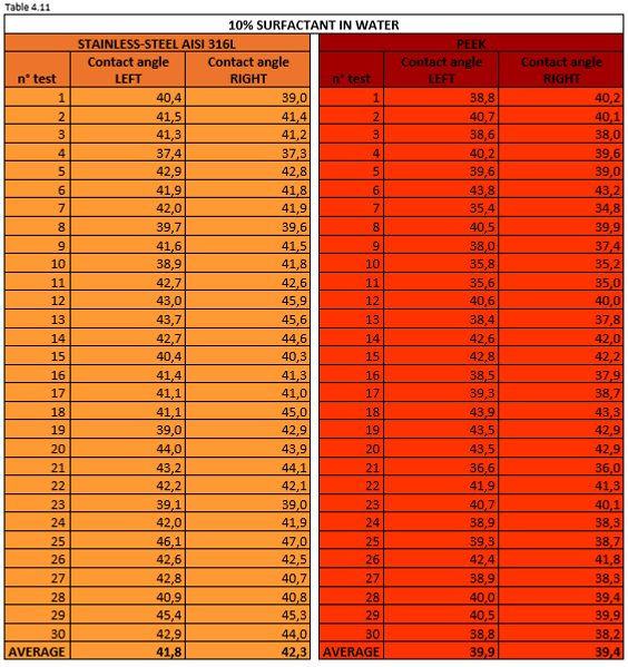
Figure 4.20 shows a 10% surfactant mixture droplet on stainless steel AISI 316L (left) and PEEK surface (right).

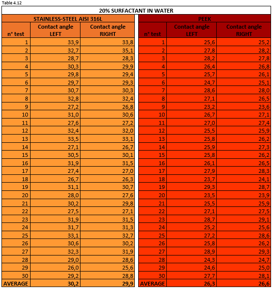
Figure 4.21 shows a 20% surfactant mixture droplet on stainless steel AISI 316L (left) and PEEK surface (right).
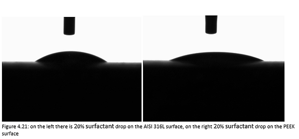
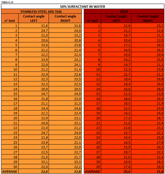
Figure 4.22 shows a 50% surfactant mixture droplet on stainless steel AISI 316L (left) and PEEK surface (right).
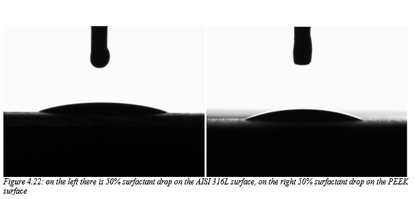
Figures 4.20, 4.21 and 4.22 are the photos of the drops of surfactant-water mixture deposited on the materials forming the valve. From these photos we can clearly see the profile of the droplet which, as the surfactant concentrations increase in water, becomes lower.
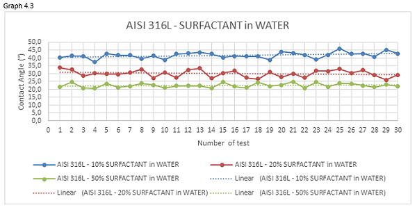
Looking at the graphs 4.3 and 4.4 we can see how the curve, representing the measurements of the 10% surfactant-water mixture, has an average value of contact angle higher than mixtures having a percentage of surfactant dissolved in water greater.

4.2.6 Mixture of water, ethanol (10% v/v) and surfactant soap (10% v/v, 30% v/v) on stainless-steel AISI 316L and PEEK surfaces
The last test involves the study of a mixture that is both disinfectant and cleaning agent. I combined the bactericidal characteristics of ethanol with the degreasing agents of the anionic surfactant. The base of the mixture remains water and the concentration of ethanol was always 10%.
I performed the wettability test with the following mixtures:
- 10% ethanol +10% surfactant + 80% water
- 10% ethanol + 30% surfactant + 60% water
Table 4.14 shows the conditions in which the wettability tests were performed. These values are the same for the two mixtures.
Tables 4.15 and 4.16 report the measurement values for the left and right contact angle of the droplet for the two mixtures mentioned above.
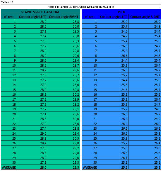
Figure 4.23 shows a 10% ethanol & 10% surfactant in water mixture droplet on stainless steel AISI 316L (left) and PEEK surface (right).

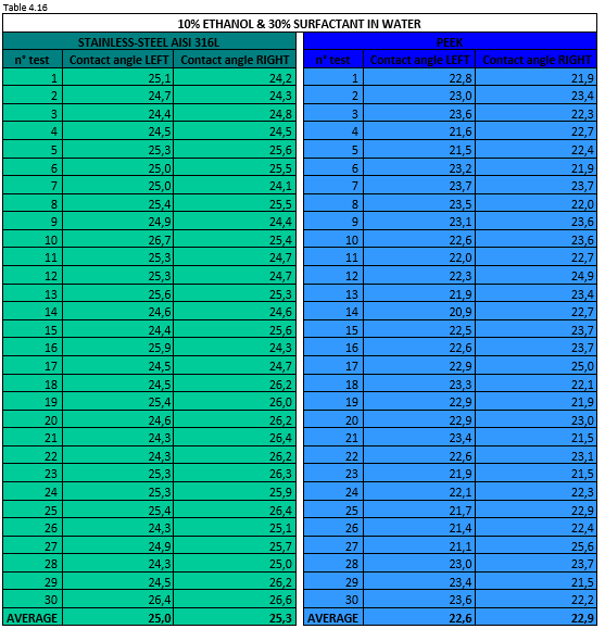
Figure 4.24 shows a 10% ethanol & 30% surfactant in water mixture droplet on stainless steel AISI 316L (left) and PEEK surface (right).
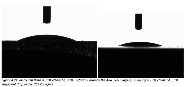
Figures 4.23 and 4.24 are the photos of the drops of ethanol & surfactant-water mixture deposited on the materials forming the valve. From these photos we can clearly see the profile of the droplet which, as the surfactant concentrations increase in water, becomes lower.
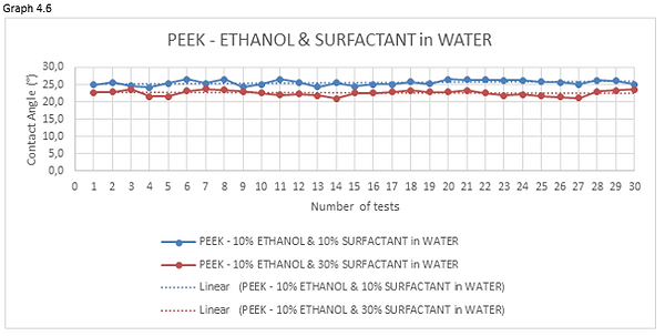
Looking at the graphs 4.5 and 4.6 we can see how the curve, representing the measurements of the 10% surfactant-water mixture, has an average value of contact angle higher than mixtures having a percentage of surfactant dissolved in water greater.

4.2.7 Results
Thanks to the wettability tests we have been able to confirm that pure ethanol forms a very low contact angle. Vice versa,water has a poor wetting power on the two hydrophilic surfaces of AISI 316L and PEEK.
Table 4.17 shows all the values of the tests for the calculation of the contact angle, valid for the two materials.

The tests also confirmed that the surface energy of stainless steel AISI 316L is very similar to that of PEEK. In fact, with the same mixtures, the values of the contact angle for both materials are very similar to each other.
These laboratory tests were necessary to select which mixture I should use during the practical simulation on the piston filler prototype.
The data shown in Table 4.17 show that the best mixture for this purpose is pure ethanol with an average contact angle of 11.70° for AISI 316L and about 10° for PEEK .
However, using pure ethanol to clean a 20 L tank is impossible for many reasons:
i) ethanol is a very volatile and explosive solvent, therefore using large amounts of this flammable liquid would be very dangerous for safety;
ii) ethanol is a polar solvent with little affinity to remove traces of greasy or oily dirt. Using only ethanol to clean traces of fat food would be ineffective;
iii) ethanol has a high cost and the need for many liters of this solvent would make the cleaning process an unsustainable cost for the company.
The second best cleaning result was obtained with a water-surfactant 50-50 with an average contact angle of 22.67° for AISI 316L and about 21.21° for PEEK.
However on a large scale (20l) it is impossible to use this ratio due to excessive foam formation and the need for a consequent prolonged rinsing with water.
For these reasons I decided to use the 10% v/v ethanol-water mixture with the addition of 30% anionic surfactant.
In previous tests, this mixture showed good contact angles (25.16° in AISI 316L and 22.75 in PEEK ).
The presence of ethanol guarantees a disinfecting and antibacterial power, which combined with the degreasing and descaling power of the surfactant foam creates an effective mixture against all the most disparate types of food dirt. The foam is essential because increases the contact time of the detergent with the dirty surface, improving its effectiveness.
The low percentage of ethanol dispersed in an aqueous matrix (10%) makes this mixture safe for industrial cleaning, avoiding the danger of explosions which is present in a 100% ethanol solution.
In addition, the presence of surfactant at 30% (and not more at 50%) ensures the presence of a fair amount of foam easy to remove with rapid rinsing with water.
4.3 Technology solution: experimental approach with piston filler prototype
4.3.1 Piston filler prototype
The piston filler prototype is a reduced scale machine that has the task of simulating this type of filling through a single piston.
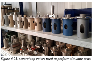
The materials forming the prototype are the same that we find in the DB piston filler: stainless steel AISI 316L and the tap valve in PEEK. However, on this prototype we can also test valves with materials different from the PEEK, such as calcium fluoride-loaded Teflon or non-certified materials such as some bronze alloys.
Figure 4.25 shows some of them.
The prototype works in this way: from the top, the tank is filled with the food product.
The machine is switched on and the piston starts to move. During the ascending phase of the piston (suction phase) a device patented by Zilli&Bellini simulates the rotation of the valve closing it.
During the piston descent phase (pressure phase), this device rotates the valve opening it, but preventing the leakage of food product from the filler valve
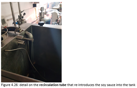
In fact, this device recirculates the food product using a tube that ends in the tank. The pressure generated by the thrust of the piston is enough to allow fluid recirculation.
Video 4.1 shows how the device work
Video 4.1
Instead in Video 4.2 the prototype is filmed while it is on.
Video 4.2
A continuous loop is created. The food product contained in the tank is aspired by the piston and inserted into the cylindrical structure in which the piston moves. Then the device simulates closing the filler valve and connects the piston to the tank. When the piston pushes down the food product, the device simulates the opening of the filling valve, but without the leakage of the food product, which will be introduced back into the tank, creating a continuous recirculation. (Figure 4.26)
After 4 hours of continuous work, I decided to turn off the prototype and manually opening the valve under the tank, I slid out the soy sauce using a drain pipe and collected in other tanks for a possible future reuse.

From this point I simulated a washing cycle alternating rinses to cleaning with the mixture 10% ethanol & 30% surfactant in water.
Schematically the cycle consists of these phases:
i) When the prototype is off, the tank is filled with water avoiding the overflow and after that the valve under the tank is immediately open (Figure 4.27). In this way the mass of water flows down and removes the coarser residues of the food product.A mobile drain pipe discharges the first rinse into an adjacent sink.
ii) The prototype is turned on, then the piston is activated and the device that simulates the rotation of the valve starts to work. The tank is filled from the top with water at room temperature, which after encountering the tap valve, is recirculated by the device. A water rinse loop is created. This recirculation of water lasts 15 minutes and is used to remove the soy sauce from the tank and from the recirculation tube. (Video 4.3)
Video 4.3
After 15 minutes, the valve under the tank is open and the fluid formed by water and soy sauce residues is discharged into the adjacent sink. (Video 4.4)
Video 4.4
After 15 minutes, the valve under the tank is open and the fluid formed by water and soy sauce residues is discharged into the adjacent sink. (Video 4.5)
Video 4.5
iii) The tank is filled by the mixture of 10% ethanol & 30% surfactant in water, while the prototype is worked and the valve under the tank is closed. The cleaning loop lasts about 30 minutes. (Video 4.6)
Video 4.6
After this period, the valve under the tank is open to allow the mixture to flow out. The drain pipe containing chemical solvents ends in a special container for disposal.
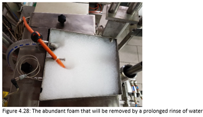
As mentioned before, the surfactant produces foam (Figure 4.28) which must be removed thanks to a rinsing with water. Furthermore, the final rinse has the task of washing the surfaces in order to remove the residues left by the mixture.
iv) Final water rinse
It is the rinse that has more waste of water because the valve under the tank is always open, so that there is no recirculation. Water is introduced from the top of the tank while the prototype is in operation. The water wets the inner surface of the tank to drag residues of the mixture with it. The water must also eliminate the foam created by the mixture.
After 20 minutes the prototype is turned off and the last liters of dirty water are discharged.
4.3.2. Results
I simulated a short wash cycle, used by companies before a product change. The overall duration of the cycle was just over 65 minutes for a 4 hours prototype use.
The scope was to test the mixture with 10% ethanol & 30% surfactants in water and see if it had enough cleaning power to remove dirt from the tap valve.
The mixture was not entirely capable of removing soy sauce from all parts, especially in the areas under the gaskets. The tap valve surface is perfectly cleaned after the washing process but under the gaskets we can noticed small traces of residual soy sauce. (Figure 4.27).
If we compare the Video 4.5 and Figure 4.29, we can see a great improvement of the final cleaning level.
Cleaning under those gaskets is almost impossible, or rather it can become possible if the filler valve is re-designed. This would mean changing the position of the filler valve in the piston filler, changing its geometry and orientation. But in this Master's Project the challenge was to find a way to clean the filler valve not changing its design or materials.
With this mechanical design limitation, I could only search a liquid that could be used inside a cleaning cycle to enter in the thin space between the tap valve and its stainless steel body.To enhance the wettability of the cleaning mixture used I focus on a mixture of 10% ethanol & 30% surfactants in water. The presence of ethanol decreases the contact angles of the mixtures and adds to the mixture an antibacterial and disinfectant power. The surfactant produces a compact foam useful for removing the oily traces of food product.
The results obtained are promising:I improved the degree of cleanliness for the filler valve that Zilli&Bellini obtained with other chemicals (such as soda), using more safety and environmental friendly solvents.
However, this mixture could be further improved, for example by better balancing the percentage ratio of water, ethanol and surfactant to reduce the amount of foam (and consequently the final rinse time) without reducing the cleaning power of the mixture.

5. Suggested Future Work
The prototype test had good results. The mixture has apparently been able to clean most of the filler valve surface.
Every time you create a new wash cycle or use new sanitizing agents or change the machines design to be cleaned, you must ensure that the clean surface is effectively sanitized. The values of microbial charges must be below the limits set by the ISO 18593: 2004 standards.
For this reason, swabs must be exerted on the critical parts of the machine after the washing cycle. If the washing cycle has been well designed and the correct sanitizing agents have been used, the swabs must be negative in the presence of pathogenic or alterative microorganisms.
Unfortunately, in this Master's Project I could not verify through laboratory tests if this new mixture has a sanitizing power, strong enough to kill the unwanted microorganisms that can hide in the thin gap of the filler valve.
Due to lack of time I could not perform any other tests on the prototype. It would been interesting to use other types of food. In this way I could see how the mixture behaved to clean fat, dense or acidic foods. Performing many tests on the prototype using different foods, means checking the cleaning power of the mixture, with the possibility of modifying the percentages of ethanol or surfactant in relation to the nature of the food.
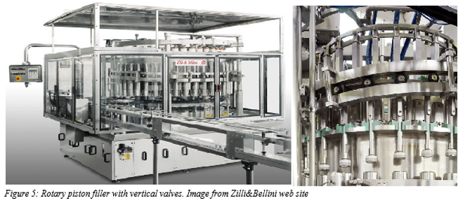
Perhaps the real solution to the cleaning problem of this valve is the redesign of the piston filler; it means to change the geometry, orientation and position of the filler valve inside the piston filler. For this reason, Zilli & Bellini has recently placed on market the rotary piston filler with vertical valve. This machine has a greater ease of cleaning than the piston filler described in this Master's Project.
Redesign just one part of this machine would have been complicated. I should have changed only the filling valve and left the other piston filler components unchanged. For this reason, in this Master's Project I looked for a solution that did not require a redesign of the machine.
However, even if this mixture will not be used within a washing cycle, it can be used as a sanitizing liquid for external surfaces or for cleaning tools. This mixture has excellent cleaning power as shown in the prototype test.
6. References:
[1] https://www.zilli-bellini.com/
[3] https://www.ensingerplastics.com/en/shapes/products/peek-tecapeek-natural
[4] http://www.manifatturacattaneo.it/p/PEEK/PEEK
[5] http://www.ravaniacciai.it/aisi_316l/listtables_en_101.aspx
[6] HJ Heinz, Principles and Practices for the Safe Processing of Foods, edited by David A. Shapton and Norah F. Shapton, Butterworth-Heinemann Ltd, 1991
[7] M. Kalin and M. Polajnar, "The wetting of steel, DLC coatings, ceramics and polymers with oils and water: the importance and correlations of surface energy, surface tension, contact angle and spreading”, Applied Surface Science,Vol.293, pp.97-108, February 2014
[8] Yuehua Yuan and T. Randall Lee, Surface Science Techniques, by Gianangelo Bracco, Springer Series in Surface Science, Vol. 51 , Gianangelo Bracco and Bodil Holst Editors, 2013
[9] Jaroslaw Drelich, "Guidelines to measurements of reproducible contact angles using a sessile-drop technique " in Surface Innovations, Vol. 1, Ice Publishing, pp. 248-254, December 2013
[10] Jean-Claude H. Hautemont, “Cleaning system for filler”, US Patent number: 4,534,494, assigned by Societe Anonyme Dite: Etude Et Realisation De Chaines Automatiques ERCA, Orsay, France, Date of Patent August 1985
[11] Stanley A. Groom,” Cleaner for filler nozzles”, US Patent number: 4,987,934, assigned by FMC Corporation, Chicago, Unites States, Date of Patent January 1991
[12] Antonio Bartolotta, Meccanica dei fluidi,EdiSES, University of Palermo, Italy, 2015
[13] Treccani Encyclopedia: http://www.treccani.it/
[14] Cassol Michele, Study of the wettability of surfaces patterned with nano fibers, University of Padova: UNIPD,2014